Transmission Media in Computer Network ,Categories of Transmission Media, UnGuided Media in Transmission Media, Types of Propagation Modes, Packet switching, Types of waves
PART 2
TRANSMISSION MEDIA :
UNGUIDED MEDIA: WIRELESS
Electromagnetic Spectrum for Wireless Communication :
 |
| Fig. Electromagnetic spectrum for wireless communication |
Types of Propagation :
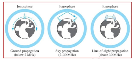
1. Ground Propagation:
- In this method, low-frequency radio waves travel close to the Earth’s surface, following the curvature of the planet.
- These signals radiate from the transmitting antenna in all directions, and the distance they cover depends on the power of the signal—the higher the power, the farther the signal can travel.
2. Sky Propagation:
- Higher-frequency radio waves are transmitted upward into the ionosphere, where they are reflected back to Earth.
- This method enables long-distance communication with relatively low power.
3. Line-of-Sight Propagation:
- In this method, very high-frequency signals are transmitted directly between antennas in a straight line.
- The antennas must be properly aligned and either tall enough or close enough to avoid being affected by the curvature of the Earth. This method is more complex because radio waves can’t be perfectly focused.
Frequency Bands :
Radio Waves :
Characteristics of Radio Waves:
- Omnidirectional Propagation: Radio waves are mostly omnidirectional, meaning they spread out in all directions from the transmitting antenna. The sending and receiving antennas don’t need to be aligned for successful communication, as any receiving antenna in range can pick up the signal. However, this characteristic also leads to a disadvantage: interference. Multiple antennas transmitting on the same frequency or band can interfere with one another.
- Long-Distance Travel: Radio waves, especially those that propagate in the sky mode, can travel long distances, making them ideal for applications like AM radio broadcasting.
- Penetration of Walls: Radio waves, particularly those with low and medium frequencies, can penetrate walls. This is useful because devices like AM radios can receive signals indoors. However, it can also be a disadvantage, as signals cannot be restricted to only the inside or outside of a building, leading to potential signal leakage.
Limitations:
- The radio wave band is relatively narrow, just under 1 GHz. When divided into sub bands, the limited width of these sub bands results in low data rates for digital communications.
- Most of the radio wave spectrum is regulated by government authorities, like the FCC in the United States and Department of Telecommunications (DoT) & Telecom Regulatory Authority of India (TRAI) in India. Any use of this spectrum requires official permission.
- Licensed Frequency Bands: FM band is licensed between 88-108 MHz for radio broadcasting and Unlicensed Frequency Bands: Wi-Fi: 2.4 GHz, 5 GHz band.
Omnidirectional Antenna:
- AM and FM radio
- Television broadcasting
- Maritime radio
- Cordless phones
- Paging systems
 |
| Fig. Omnidirectional antenna |
Microwaves:
- Unlike circuit-switched networks, packet switching does not reserve any specific resources like bandwidth or processing time for the packets.
- Resources are allocated only when needed, and packets are processed on a first- come, first-served basis.
- Since there is no dedicated path or reserved resources, packets might experience delays. For instance, if a switch is busy processing other packets, newly arrived packets must wait their turn, which can increase transmission time.
Frequency Range: From 1 GHz to 300 GHz.
Characteristics:
Microwaves require line-of-sight transmission, meaning the transmitter and receiver must be directly visible to each other. They are less effective in penetrating obstacles like buildings.
 |
| Fig. Unidirectional antennas |
Applications:
Satellite communications, radar systems, and microwave ovens. In networking, microwaves are used for point-to-point communication links and cellular networks.
Infrared :
Frequency Range: From 300 GHz to 400 THz.
Characteristics:
Infrared signals are used for short-range communication and do not penetrate walls, making them suitable for indoor use. They are highly directional and require line-of-sight transmission.
Applications:
Remote controls, short-range data transmission (such as between computers and peripherals), and infrared sensors for detecting heat in security systems or medical devices.
PACKET SWITCHING :
In data communication, when a message needs to be sent from one end system to another through a packet-switched network, it must be divided into smaller units called packets. These packets can be of either fixed or variable sizes, depending on the network and the protocol being used.
reKey Features of Packet Switching:
1. No Resource Allocation:
2. Possible Delays:
Types of Packet-Switched Networks:
- Datagram Networks: In these networks, each packet is treated independently, and it may take different routes to reach the destination.
- Virtual Circuit Networks: These networks establish a pre-determined path before any data packets are sent, ensuring all packets follow the same route.
Datagram Networks :
Key Features of Datagram Networks:
How Datagram Networks Work:
 |
| Fig. A datagram network with four switches (routers) |
Routing Table :
 |
| Fig. Routing table in a datagram network |
Destination :
Delay :
- Transmission Time: The time to send a packet from one point to another
- Propagation Delay: The time it takes for the signal to travel through the medium.
- Waiting Time: Time spent at routers before being forwarded.
 |
| Fig. Delay in a datagram network |


